
Walter Lackey
Mechanical Engineering Technology
Drivetrain
Aside from providing power to the rear wheels of the Scarab, the drivetrain had two main design objectives. first to withstand and make efficient use of the powerful 5300kv motor, second to maintain the modularity of the vehicle. The outcome is a robust drivetrain unit that shows no signs of strain so far and installs in under one minute
The majority of the components on the drivetrain are store bought such as gears shafts and bearings. the rest of the drivetrain is made with 3D printed ABS plastic or 6061 aluminum for the differential housings.

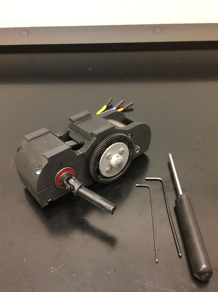
Fully assembled Drivetrain with tools needed for assembly
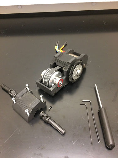
Semi-exploded view - shows power transmission functionality
Exploded View
-
All nuts are captured, meaning that they cannot spin in place, which reduces number of tools needed for take-down and assembly
-
Drivetrain can be reassembled in under 2 minutes needing only three tools to do so.
-
Asterisked parts were custom made by myself at CWU

A. (1x) Atomik Red 540 6.5T 5300kv brushless motor
B. (1x) 3D printed support structure
C. (1x) Redcat Racing 48 pitch 15 tooth pinion gear
D. (1x) HPI racing 48 pitch 96 tooth spur gear
E (1x) custom 6061 aluminum gear to shart mounting flange
F. (1x) 0.24970" Dia. 3" Long, 416 Stainless Steel Shaft
G. (1x) 20 groove 9mm wide 3mm gt2 timing belt pulley
H. (1x) 63 groove 9mm wide 3mm gt2 timing belt
C
A
B*
D
F
E*
G
H
I
J*
K*
L
M
N
O*
P
Q
I. (2x) R4A-2RS Bearing 1/4"x3/4"x9/32" inch sealed
J. (1x) custom steel collar and set screw
K. (1x) differential (disassembled)
L. (2x) size 608 Bones reds skateboard bearings #BSACBR88
M. (4x) number 4 nuts for differential
N. (2x) threaded drive shaft pin
O. (1x) differential cap
P. (2x) Traxxas splined U-joint driveshaft
Q. Tools required to reassemble drivetrain from shown image
Design
The start of the design process is to define the overall design parameters numerically. These values were obtained by researching the specifications and performance of high end RC cars produced by companies such as Traxxas and Team Losi. From this research a set of requirements were determined that would ensure that the drivetrain fits within the overall design parameters.
Some of the most difficult tasks in the design process included determining the proper drive belt, component availability, and component clearance. Using a belt drive system has the advantages of being able to absorb motor torque impulses, and allows for loose tolerances compared to gears. Difficulties arose when determining the belts torque holding capacity. The result of the analysis was a static torque value just short of the requirement.
There were many points of the design where a component was needed that was either too expensive, or unavailable. Some portions of the design ended up being determined solely by component availability. This process took hours of research and recalculation
Design Process

Drivetrain Requirements
-
Motor temperature must stay under 160°F when held at half throttle for as long as a fully charged 5200mah LiPo battery lasts.
-
Drivetrain must allow the car to reach a speed of no less than 30mph
-
Drivetrain must be able to resist 24 in-lbs of static torque with the wheels held fixed for 24 hours
-
Drivetrain must not exceed a height of 2.5” from the top of the chassis.
-
Differential must withstand the heat and stress of half throttle operation while holding alternating drive wheels still for 5 seconds at a time, for 1 minute.
Drivetrain Installation
The installation of the drivetrain to the chassis is easily one the the most unique features of the Scarab. In order to work with the inherent strengths of the 3D printed material, a clamp mounting system was used instead of screws. Using a clamp allowed an increase in mounting force by spreading this force out over a large surface area. The support structure was also printed so that the material layers horizontally, therefore the clamping force compresses these layers together. This greatly reduces the risk of layer separation which is the most common failure mode for this material. the three images below show the entire installation process

-
Place drivetrain between camber towers and over the mounting studs.

2. Align driveshaft splines and press drivetrain down onto the chassis.

3. Set drive clamp over mounting studs and fasten the two lock nuts.
4. Snap color coded wires from the motor to the ESC.
Design Evolution
The design of the drivetrain changed many times due to clearance issues or parts availability. While the majority of the component changes are undocumented, the updates in the 3D printed parts can be seen in the following images.

All the attempts at 3D printing the Differential carriers, Support Structure, and the first version of the Side Housings.


Above images show the second version of the Support Structure and Differential Cap with the first version of the Side housings on the differential.